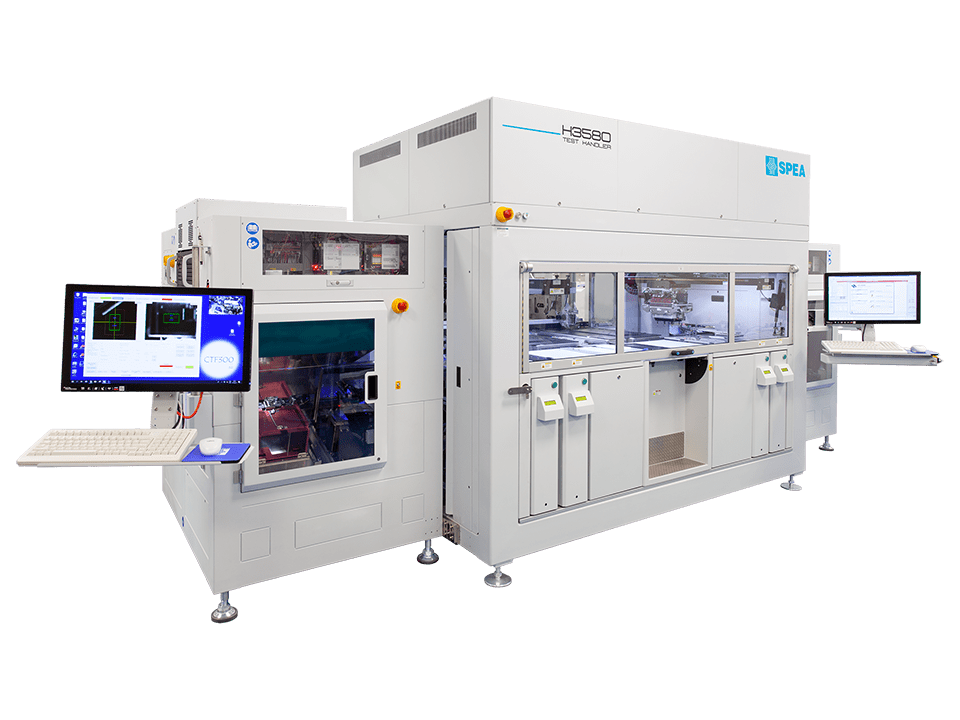
SPEA has developed dedicated equipment to thoroughly test every individual die after the wafer dicing. Comprehensive KGD test cells fulfill static and dynamic test requirements of low- and high-power devices at KGD level. They include precise parametric testing, optical test, automatic handling from and to the diced wafer, device contacting, and temperature conditioning.
Wafer-level testing is not enough
The parametric testing normally executed on the die at wafer level is not sufficient to eliminate the failure rate, due to the die-to-die interference that can affect the test performance, the impossibility to reach the voltage and current ratings required by power components, the impossibility to perform all the necessary dynamic measurements to ensure that the device’s performances meet the datasheet specifications. This will inevitably turn into yield loss, defective assemblies, parametric drift, on which we need to add the risk of defectiveness introduced by the dicing operation.
Dedicated KGD Testing Equipment
SPEA’s KGD Test Cells are specifically designed to combine full test coverage and precise parametric testing with the throughput and automation required by high-volume manufacturing processes. The outcome is fully tested, qualified IC devices, able to meet the full datasheet specifications with zero defects.
100% test coverage at KGD level, also for power components
The KGD Test Cells perform not only a complete DC parametric testing, but also AC testing, UIS/UIL Avalanche, RG/CG and Short Circuit testing.
In order to perform the dynamic tests that verify the device switching parameters, the test equipment is able to condition the device under test with both high current and high voltage simultaneously. To prevent any possible danger due to the high power dissipation, the test cell is equipped with a full range of protections, including overcurrent and overvoltage protection circuits, voltage monitors on output relays commands, open/short check, contact needle protection.
25nH parasitic inductance, along the whole connection chain
Tester connection layout, sockets and contactors are designed to minimize the distance between device under test and test instrumentation, and to guarantee the lowest possible values of stray inductance along the whole signal path. The possibility of voltage overshoots during the commutation is minimized, since the possible overvoltage values are always lower than the breakdown voltage, under any circumstance.
Precise probing, with no electrical arcing
The test chambers are conditioned with a compressed air atmosphere, and specifically designed to suppress any electrical arcing phenomenon that would damage devices and test equipment.
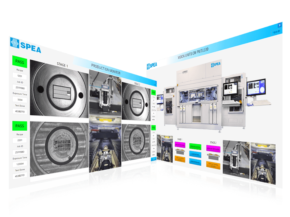
To ensure the precise probing on singulated dies, a fine pitch probe alignment is performed, based on a world-class vision alignment. The probe system automatically aligns each die prior to testing, to eliminate any variation in X, Y and Theta rotation of its position.
Automatic handling from diced wafers

Pick&Place Handlers
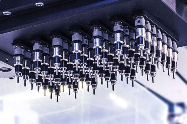
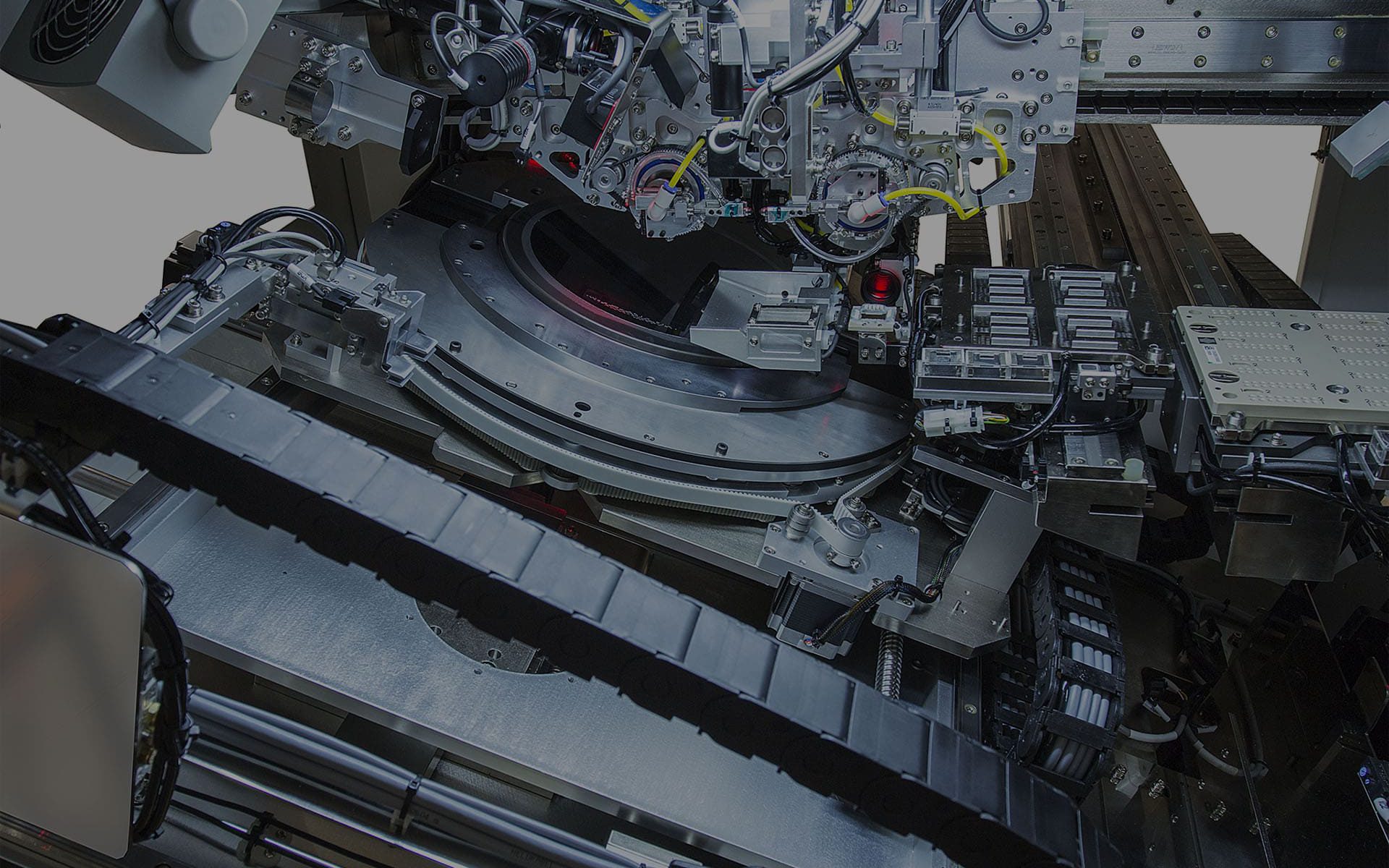
Integrated pick&place heads, based on linear motion technology, are used to guarantee fast and accurate handling. The components are moved from the wafer (on blue tape or UV tape) to the test chamber, where they are contacted and fully tested.
After the test, the good dies can be placed on a film frame, reconstituting the original wafer format, or they can be packaged in tape on reel after an accurate optical inspection. The same machine configuration can be flexibly used with both the output options, with no need for setup changes.
Turret Handlers
A turret-based structure offers great configuration flexibility in a compact size, to perform high-speed and high-accuracy test, inspection and finishing.
The possibility to handle diced dies directly from film-framed wafers, with output on reconstructed wafer or finishing on tape, makes this solution an ideal choice for KGD testing. The handler includes multiple stations for electrical tests (up to 10), with thermal conditioning option to test at temperature.

Optical and geometrical test
Optical inspection on the six sides of the devices is performed prior to the electrical test, to verify the component presence and position, track the devices through their ID code, and screen out components that present dimensional, cosmetic or mold defects.
Vision inspection from top and bottom is performed also on the test stage, to verify the device presence and alignment, while an accurate laser measurement allows the equipment to control the probing force and compression.
A further complete optical inspection can be performed on the output stage, after the test. When the finishing on tape is performed, in-pocket inspection and tape seal inspection are performed as well, to guarantee that the devices can be shipped directly to the customer, with no need for further verifications.
Temperature conditioning
Temperature testing is often needed to detect defects in devices that are responsive to thermal variations, or to apply the testing conditions required, for example, by automotive standards.
SPEA test cells incorporate a flexible, nitrogenless thermal conditioning system that can heat or cool parts in the temperature range of -50 to +180°C. Dedicated temperature control per site avoids temperature spread between the different devices under test, ensuring uniform test conditions for all the devices.


